
0
Owner's of the Empire Comfort Systems Grinder 23-700 gave it a score of 0 out of 5. Here's how the scores stacked up:

POWER CONNECTIONS
A separate electrical circuit should be used for your tools. This circuit should not be less than #12 wire and should be
protected with a 20 Amp time lag fuse. If an extension cord is used, use only 3-wire extension cords which have 3-prong
grounding type plugs and 3-pole receptacles which accept the tool’s plug. For distances up to 100 feet, use #12 wire.
For distances up to 150 feet, use #10 wire. Have a certified electrician replace or repair damaged or worn cord immed-
iately. Before connecting the motor to the power line, make sure the switch is in the “OFF” position and be sure that the
electric current is of the same characteristics as stamped on motor nameplate. All line connections should make good
contact. Running on low voltage will injure the motor.
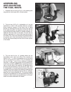
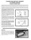
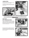
GROUNDING INSTRUCTIONS
CAUTION: This tool must be grounded while in use to
protect the operator from electric shock. The motor is
shipped wired for 120 Volt, Single Phase and is equipped
with an approved 3-conductor cord and 3-prong ground-
ing type plug to fit the proper grounding type receptacle,
as shown in Fig. 12. The green conductor in the cord is
the grounding wire. CAUTION: Never connect the
green wire to a live terminal.
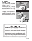
An adapter, shown in Fig. 13, is available for connecting
3-prong grounding type plugs to 2-prong receptacles.
THIS ADAPTER IS NOT APPLICABLE IN CANADA.
The green-colored rigid ear, lug, etc., extending from the
adapter is the grounding means and must be connected
to a permanent ground, such as to properly grounded
outlet box, as shown in Fig. 13.
CAUTION: IN ALL CASES, MAKE SURE THE RECEP-
TACLE IN QUESTION IS PROPERLY GROUNDED.
IF YOU ARE NOT SURE, HAVE A CERTIFIED ELEC-
TRICIAN CHECK THE RECEPTACLE.
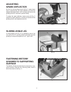
MOTOR AND SPEEDS
A 1/5 H.P. motor is supplied with the Wet/Dry Grinder. The
5 grinding wheel operates at 3450 RPM and replacement
wheels should be rated for 3450 RPM or higher. The 10
grinding wheel operates at the slow speed of 70 RPM.
6
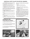
CONNECTING WET/DRY GRINDER
TO POWER SOURCE
Fig. 12
Fig. 13
Fig. 14
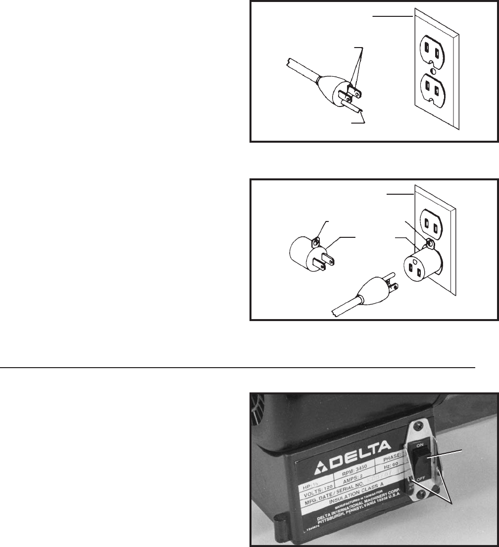
SWITCH
The switch (A) Fig. 14, is located under the grinder motor.
When the switch is pushed to the “ON” position, both
grinding wheels will turn. To stop the grinding wheels,
push the switch to the “OFF” position. IMPORTANT: We
suggest when the grinder is not in use, the switch be
locked in the “OFF” position, using a padlock thru the two
holes (B) in the switch plate.
GROUNDED OUTLET BOX
CURRENT
CARRYING
PRONGS
GROUNDING BLADE
IS LONGEST OF THE 3 BLADES
GROUNDED OUTLET BOX
GROUNDING MEANS
ADAPTER
A
B


Find Your Products By Category
Please Login
