

0
Owner's of the Empire Comfort Systems Grinder 23-700 gave it a score of 0 out of 5. Here's how the scores stacked up:

4
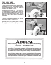
Fig. 5
Fig. 6
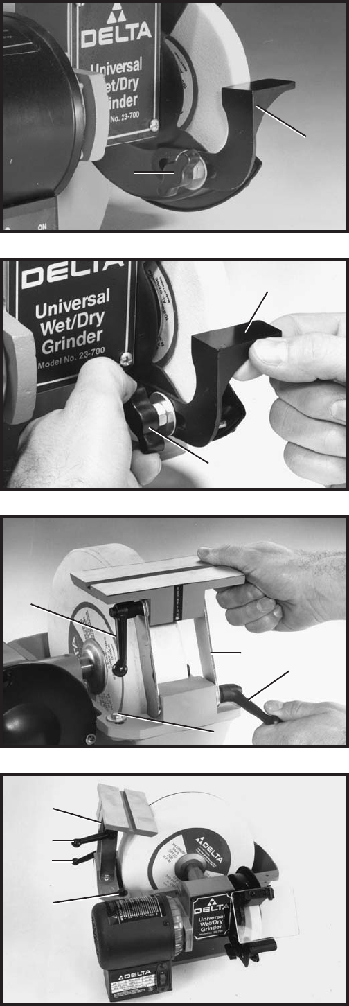
Fig. 8
Fig. 7
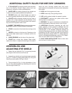
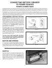
ASSEMBLING
AND ADJUSTING
THE TOOL RESTS
1. Assemble the tool rest (A) Fig. 5, to the wheel guard
using the lock knob screw (B), nut and washer.
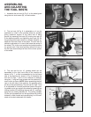
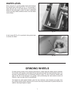
2. The tool rest (A) Fig. 6, is adjustable so it can be
positioned as close to the grinding wheel as possible
giving maximum support to the piece that is being
ground, by loosening lock knob (B), moving tool rest (A)
to the desired position and tightening lock knob (B). As
the grinding wheel wears down to a smaller diameter, re-
adjust the tool rest closer to the wheel. The tool rest (A)
should be adjusted so it is set a little below the center of
the wheel. This is the most practical and safest position
for general work. Free hand grinding without the use of
the tool rest should always be done on the lower quarter
of the wheel.
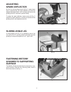
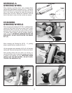
3. The tool rest for the 10 grinding wheel can be
assembled to the right hand side of the machine as
shown in Fig. 7, or can be assembled to the left hand
side of the machine as shown in Fig. 8. Assemble the
tool rest (C) Figs. 7 and 8 to the machine as desired,
using two 1 long hex head screws and flat washers (D),
one of which is shown. NOTE: When assembling the tool
rest on the left side of the machine, the grinding action
will be on the upward swing. The tool rest (C) Figs. 7 and
8, is adjustable so it can be positioned close to the grind-
ing wheel and at any angle to the wheel by loosening two
locking handles (E), adjusting the tool rest (C), and tight-
ening the two locking handles (E). The locking handles
(E) are spring-loaded and can be repositioned by pulling
outward on each handle and repositioning it on the ser-
rated nut located underneath the handle.
A
B
A
B
C
E
D
E
E
E
C
D


Find Your Products By Category
Please Login
