
0
Owner's of the Bayou Classic Cooktop DB250 gave it a score of 0 out of 5. Here's how the scores stacked up:
ASSEMBLY INSTRUCTIONS
READ ALL SAFETY WARNINGS & ASSEMBLY INSTRUCTIONS CAREFULLY BEFORE ASSEMBLING OR OPERATING
YOUR COOKER. Inspect contents in the box to ensure all parts are included and undamaged.
FOR MISSING PARTS OR ASSISTANCE, PLEASE CALL 1-800-864-6194 M-F 8am - 5pm CST.
Proof of purchase will be required.
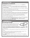
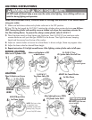
TOOLS REQUIRED:
Adjustable Wrench
9
PARTS INCLUDED:
1- Frame
2 - BG10 Burners
with Air Shutter
& Locking Nut
1- Regulator
Hose Assembly
4- PC. Extension
Leg Set
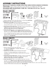
Model #DB250
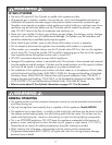
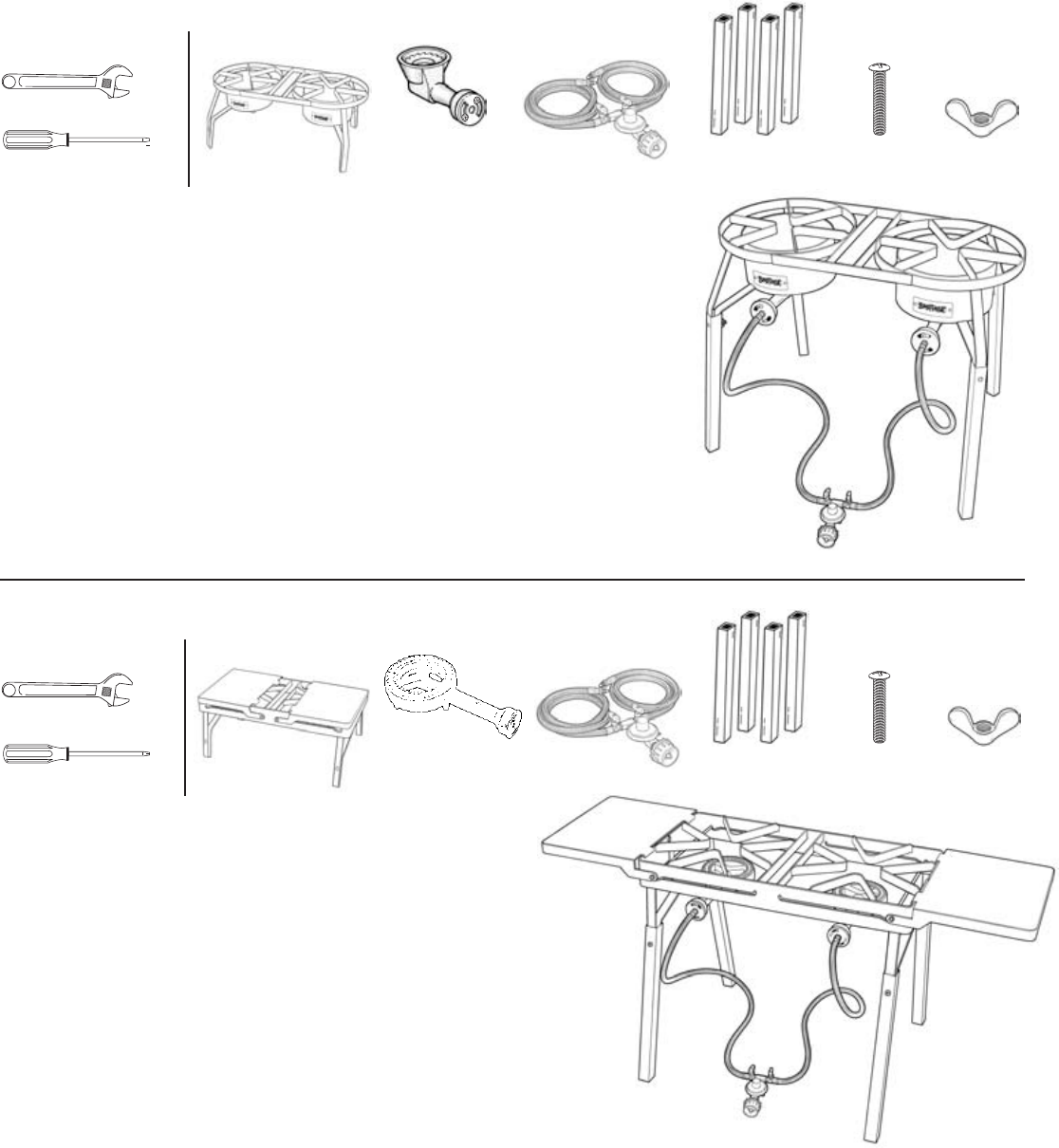
TOOLS REQUIRED:
Adjustable Wrench
PARTS INCLUDED:
1- Frame
1- Regulator
Hose Assembly
4- PC. Extension
Leg Set
Model #DB375
4- Long Bolts 4- Wing Nuts
4- Long Bolts 4- Wing Nuts
Phillips Head Screwdriver
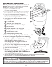
1. Remove components from the box and packing.
Turn base frame upside down.
Assemble cooker while in this upside down position.
2. Attach Burners to Crossbar - Remove locking nut from bottom of burners.
Turn burner upside down. Line up burner bolt to hole in crossbar.
Insert the bolt through the crossbar. Attach locking nut and wrench tighten.
3. Attach Extension Legs to Base Frame - Slide legs on frame to match holes at top
of extension leg. Insert long bolt and tighten with wing nuts.
NOTE: After attaching legs, return frame to upright position.
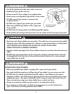
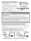
4. Attach Hose to Burner - Refer to Hose Regulator Attachment Instructions
on pages 12 - 13. NOTE: Do not over tighten brass hose connector to burner.
The air control shutter must be able to easily turn for adjustment of flame quality.
If you over tighten the brass hose connector to the burner and the air shutter
cannot turn, then unscrew the brass hose connector until the shutter can be
easily turned... Very Important!
Phillips Head Screwdriver
1. Remove components from the box and packing.
T
urn base frame upside down. Assemble cooker while in
this upside down position.
2. Attach Burners to Crossbar - Remove locking bolt from bottom
of burners. Turn burner upside down. Line up burner to hole
in crossbar. Insert the bolt through the crossbar and screw into burner.
Wrench tighten.
3. Attach Extension Legs to Base Frame - Slide legs on frame to match holes
at top of extension leg. Insert long bolt and tighten with wing nuts.
NOTE: After attaching legs, return frame to upright position.
4. Attach Hose to Burner - Refer to Hose Regulator Attachment Instructions
on pages 12 - 13. NOTE: Do not over tighten brass hose connector to burner.
The air control shutter must be able to easily turn for adjustment of flame quality.
If you over tighten the brass hose connector to the burner and the air shutter cannot turn, then unscrew the brass hose
connector until the shutter can be easily turned... Very Important!
2 - BG12 Burners
with Air Shutter
& Locking Bolt
ASSEMBLED
UNIT
ASSEMBLED
UNIT


Find Your Products By Category
Please Login
